
A situation schema is, along with the one-line schema, mandatory for every electrical inspection in Belgium. Yet, it is this document that is most often filled out incorrectly or incompletely — not because it is difficult, but because people do not know where to start. Below is a concrete step-by-step plan, from a ground plan to a schema that is ready for the inspector.
What is a situation schema precisely?
The situation schema — also known as a situation plan or installation drawing — is the floor plan of your home with the physical location of each electrical element: sockets, light points, switches, the fuse box, fixed appliances such as the stove or washing machine, and possibly the inverter for solar panels. It differs fundamentally from the one-line schema, which shows the technical structure of your installation (which circuit with which automatic switch and which cable cross-section). Simply put: the situation schema shows where everything is, the one-line schema shows how everything is connected. Both documents must be consistent with each other — the same circuit letters and the same numbering, so that an inspector can place them next to each other and immediately see that everything is correct.
Step 1: start with a correct ground plan
Draw or use a ground plan of your home, preferably to scale. This does not have to be an architectural drawing, but it must correctly represent the actual layout of the spaces — every room, door, and window in the right place. An inspector compares your situation schema with the physical installation on site; if the basic layout is not correct, it immediately raises doubts about the rest of the document.
Step 2: place each element in its actual location
Then draw each electrical point exactly where it is in reality: - sockets (including the number per connection point, if there are multiple under one cover plate) - light points and their corresponding switches - the fuse box/distribution box - fixed appliances: stove, oven, dishwasher, washing machine, dryer, heat pump, charging station - if applicable: the inverter and connection points of a solar panel installation It is essential that this exactly matches the actual installation. A schema that looks "about" like it will be rejected in case of doubt — the inspector checks point by point.
Step 3: use only the official AREI symbols
For each element, use the prescribed symbol according to AREI Book 1, Table 2.23, based on the international standard NBN EN 60617. This is not a formality: you are not allowed to invent your own symbols or mix symbols. An inspector recognizes the official symbols at a glance; non-standard symbols can lead to confusion and may be a reason for rejection. The symbols can be found via the official documentation of the Federal Public Service Economy or are automatically placed correctly if you work with drawing software.
If you cannot find the correct symbol in the AREI, you can add your own symbol or a general symbol (such as in Schematicals), but you must clearly indicate this in a legend or on the one-line schema so that the inspector immediately knows what it is about.
Step 4: connect each point to its circuit (circuit letter + sequence number)
Each socket, light point, and appliance gets the circuit letter of the power circuit to which it is connected (for example, "D"), followed by a sequence number within that circuit (D1, D2, D3,...). This lettering must be identical to what is on the one-line schema — that is precisely how an inspector can link the two documents and check if the installation matches what is on paper.
Step 5: check before submitting the schema
Review the schema before taking it to the inspection:
- Does each point on the situation schema exactly match the actual location in the home?
- Are the circuit letters and sequence numbers identical to those on the one-line schema?
- Are the official AREI symbols used everywhere, without modifications?
- Are all fixed appliances (stove, heat pump, charging station,...) included, even if they have not been installed yet but are planned?
Manual drawing versus software
Drawing a situation schema by hand is possible, but most of the errors that lead to rejection — a forgotten point, a wrong symbol, or a circuit letter that does not match the one-line schema — occur precisely because you have to keep track of everything manually and synchronize between two separate documents. With Schematicals, you draw the situation schema on your ground plan, and the corresponding one-line schema is automatically generated — including correct AREI symbols and consistent circuit numbering between both documents. This precisely eliminates the margin of error that most often leads to a comment or rejection during an inspection. 👉 Try the free trial version of Schematicals
Frequently asked questions
Is a situation schema always mandatory?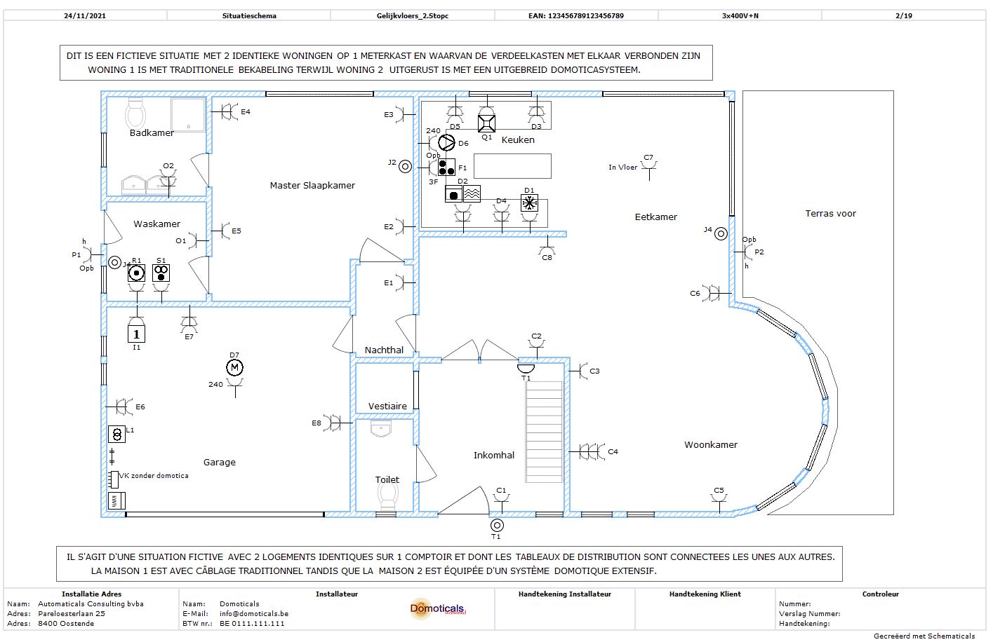
Yes, along with the one-line schema, the situation schema is mandatory for every electrical inspection in Belgium, both for new installations and for significant changes to an existing installation.
What is the difference with a one-line schema?
The situation schema shows the physical location of each element in the home; the one-line schema shows the technical structure of the power circuits. Both are necessary and must be consistent with each other.
Am I allowed to draw up the situation schema myself, or must it be done by an electrician?
You are allowed to draw it up yourself, even as a DIY enthusiast — as long as it is correct and complete according to the AREI standards. In case of doubt, it is recommended to have it checked by a professional before the inspection.